
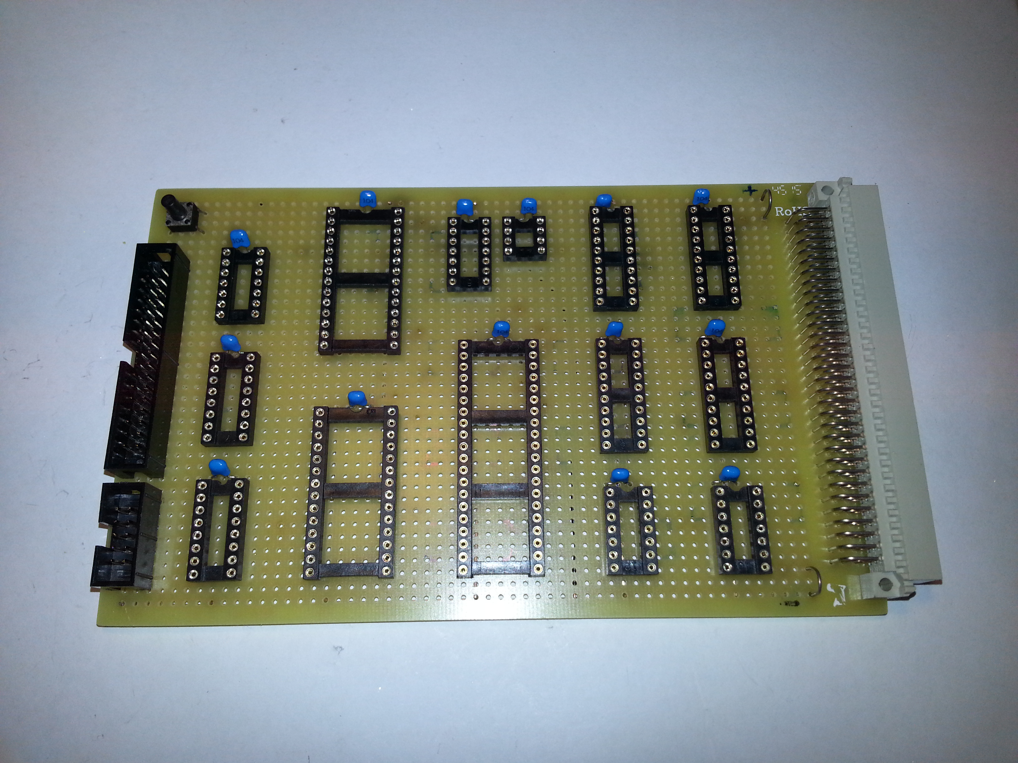
Since I was ultimately wanting to interface with the Retrobrew Computers group ECB designs, it was logical to make a prototype on a Eurocard prototyping board, so I could plug it up to the ECB backplane and test out interfacing with the other I/O boards and ensure it all worked before committing to a proper PCB.
I drew out a bit of a layout that allowed enough space for wiring without cluttering the board too much.
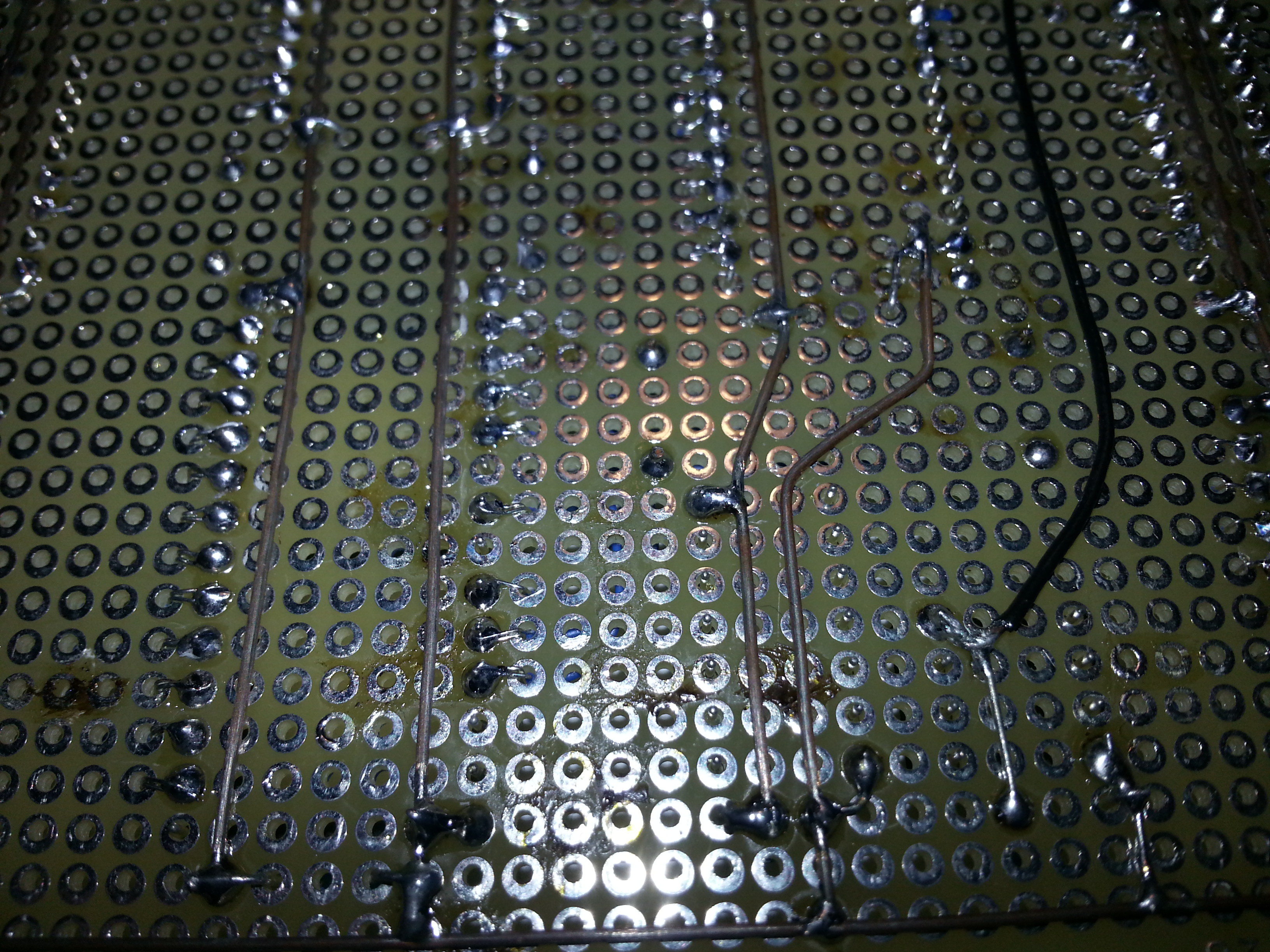
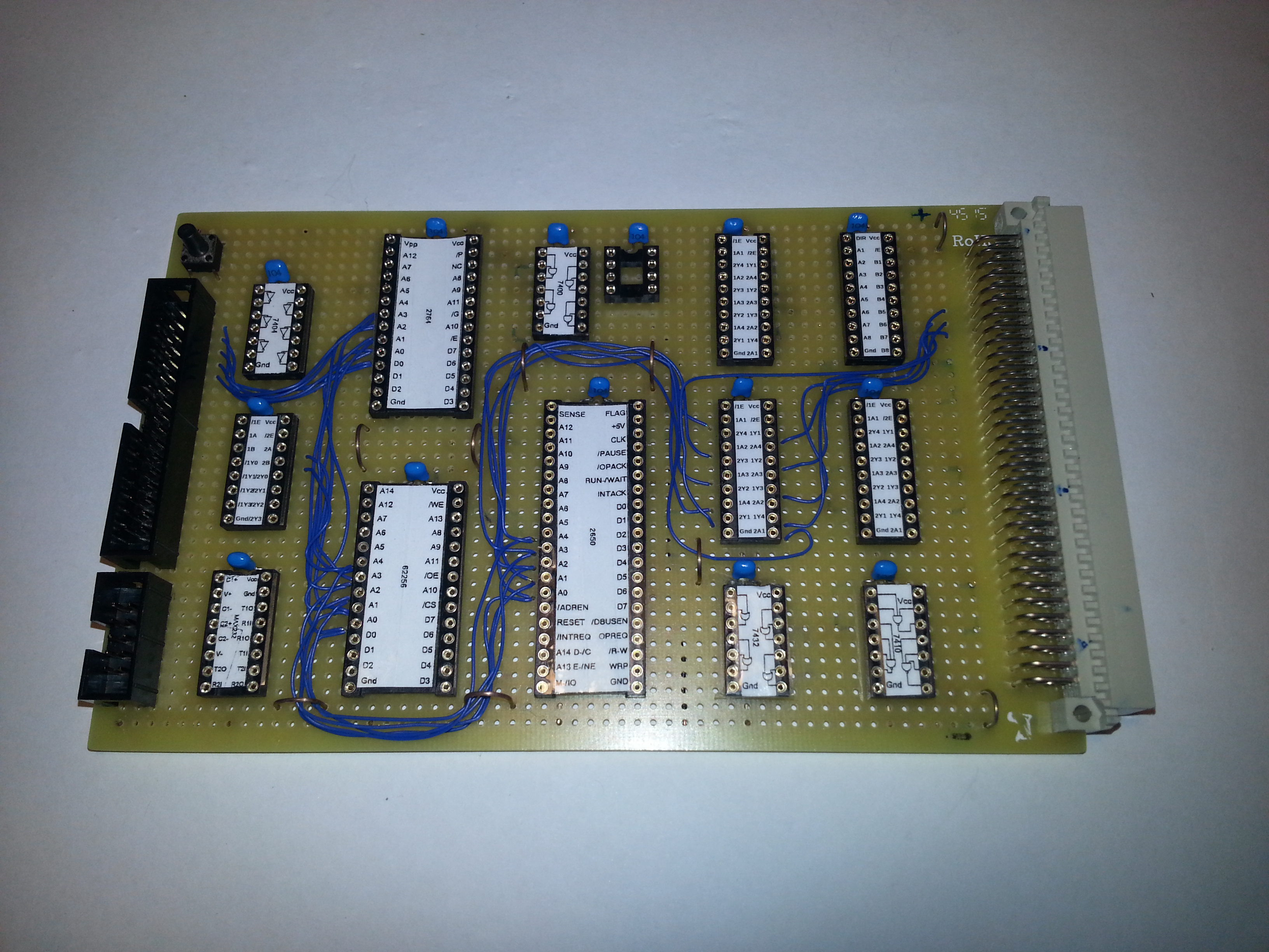
For the power rails, I ran a length of wire down each side of the board, one for the positive 5V and the other for Ground. They also line up with the power connections on the 96-pin DIN 41612 EuroCard connector, so I can power the board from the backplane. Then I ran wires up the middle of each of the chips for VCC and GND. I also threw in bypass capacitors for each chip for good measure.
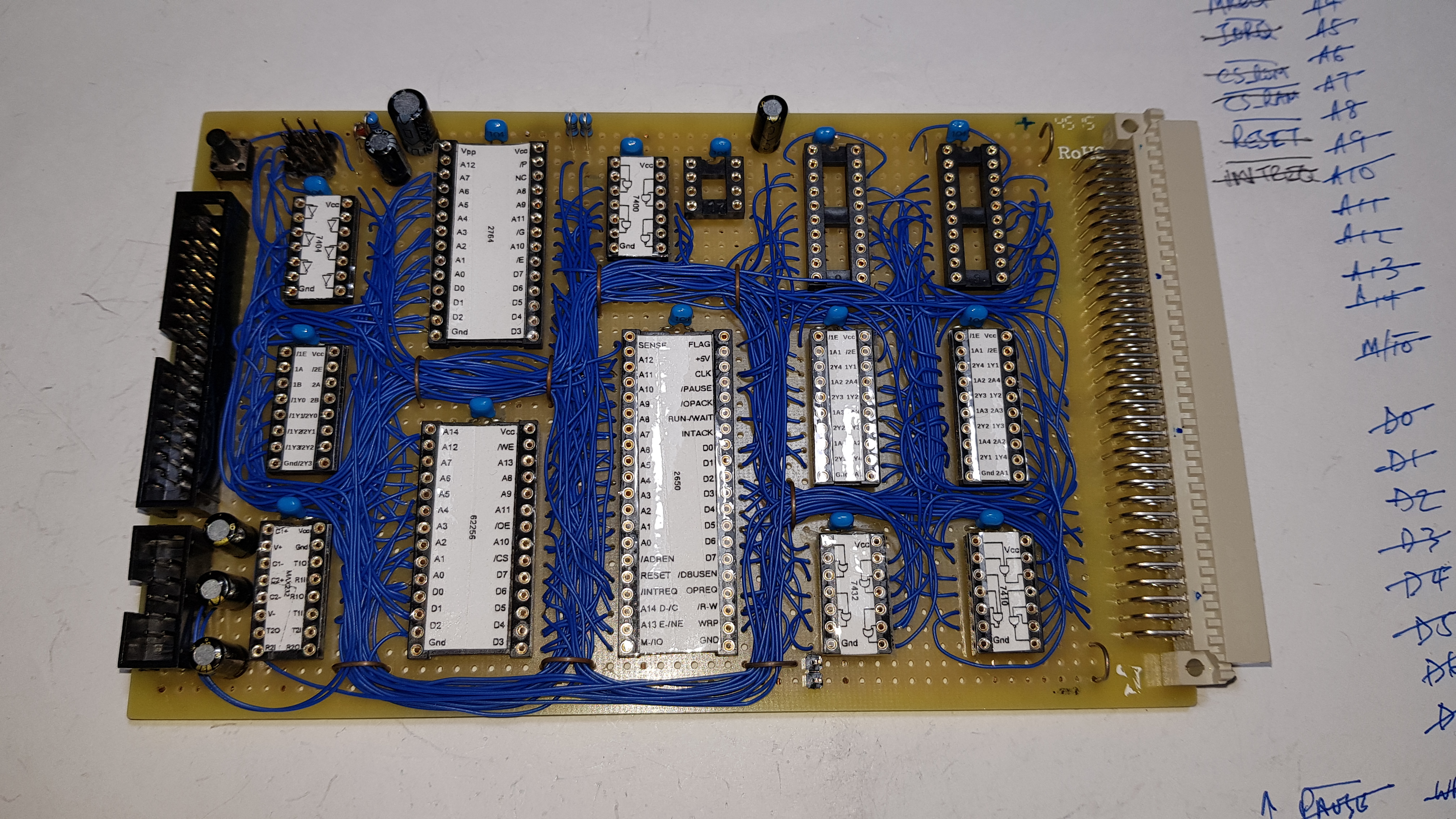
To make the board a little easier to wire, I took Grant Searle’s excellent Chip Label sheet and added a few of my own, and taped them to the sockets. This saved an enormous amount of time, not having to look back and forth to the schematic. I started with A0 and wired it to all the chips it needed to go, and then crossed it off the list. This way I would be sure not to miss any. I worked systematically through the address, data and control lines, until it was all done.
Before throwing the chips in, I did some basic short/open checking with a multimeter and checked that 5V was getting to the correct pins. Then I put in the TTL logic chips and oscillator, and powered it up to do a smoke test. All good, and a logic probe test of the oscillator finds life, so in went the CPU and memory ready for an all up test.
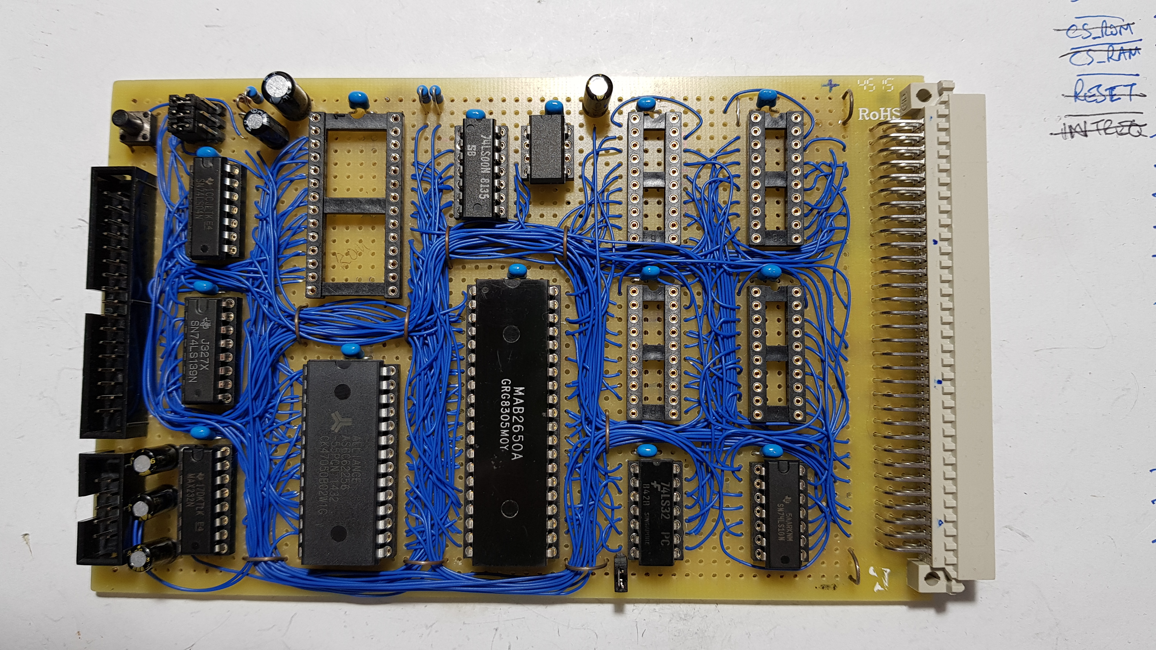
The jumpers in the top left hand corner near the reset switch, are to select the ROM size (1K, 2K, 4K or 8K). You will notice I left the ECB bus buffers out at this stage until I have made sure that the basic computer functions. I will put them in when I am ready to start testing it with an ECB I/O board (probably the DiskIO V3 board).
You will also notice the EEPROM socket has a header and cable running elsewhere and that the EEPROM is not actually in circuit. I have a ROM emulator which I can load with the boot image I want to present to the CPU, which of course will be the original PIPBUG binary for my initial tests.
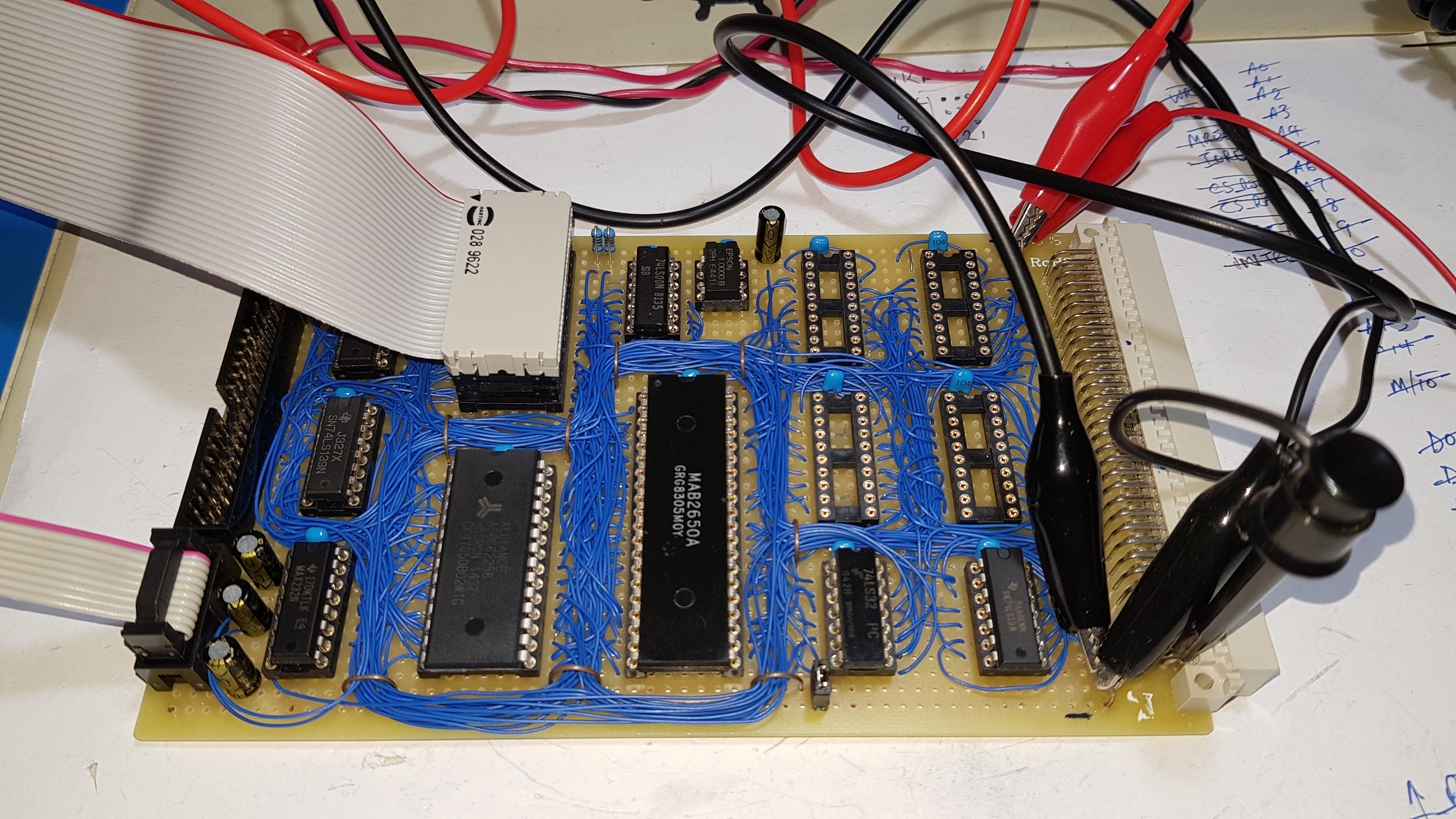
OK, so let’s see if this thing works. Switching on, hopefully expecting a console prompt, but nothing. A few clicks of the reset switch, nothing. I check for smoke and a hot chip or two, but that all seems OK. So I start probing around with the logic probe to see if there is any life. I’m not getting much from the serial output of the CPU and the main logic enable signal (OPREQ) doesn’t seem to be oscillating like I would expect it too. OK, so lets get to some troubleshooting.
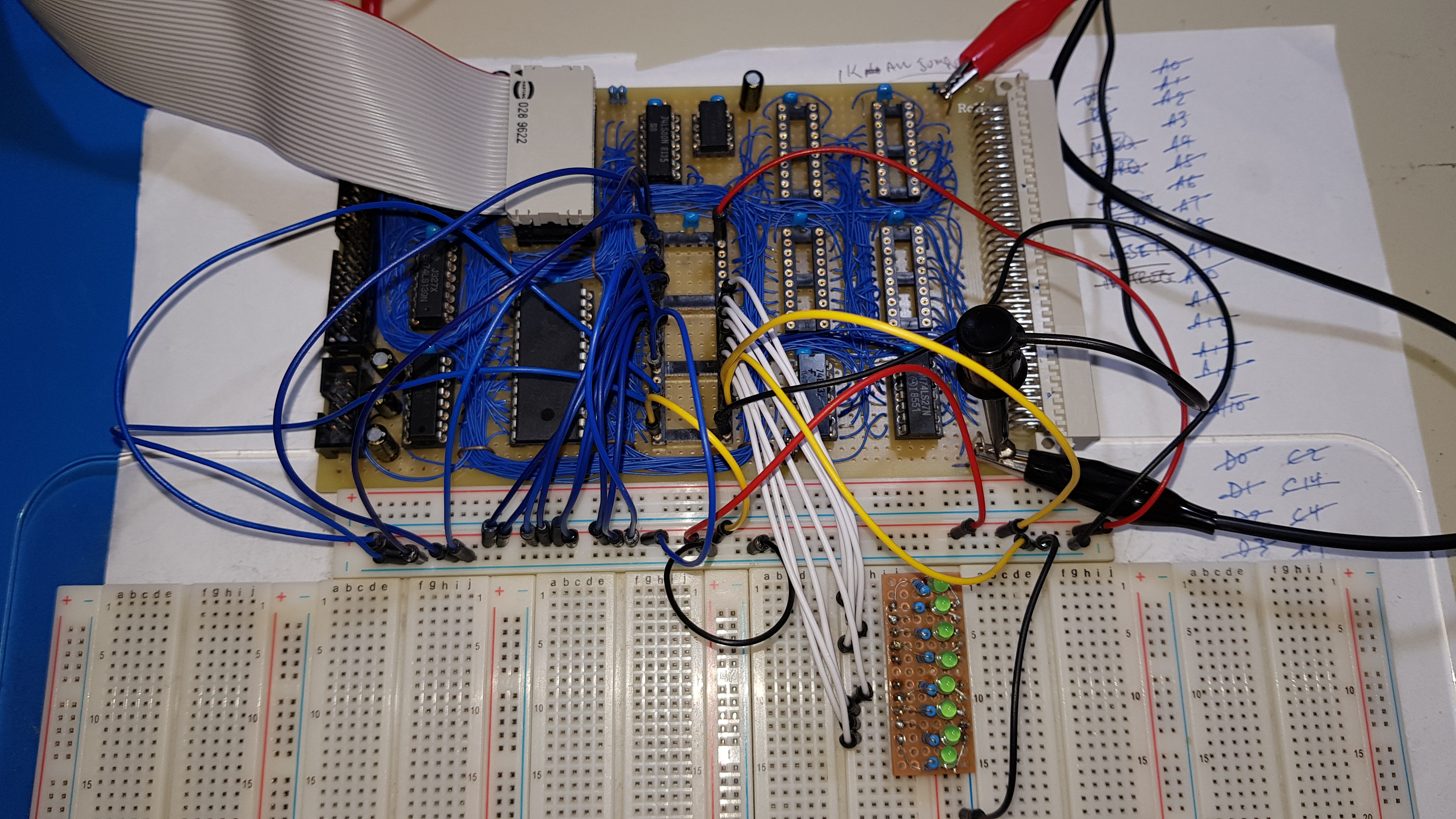
I wired up some LEDs on a breadboard and just used jumpers for the address bus and plugged them into the CPU socket. White wires are the data lines, blue for the address lines and yellow for control. I can use the address lines to step through the ROM image and use the LEDs to verify what the CPU is seeing on the data lines. Doing this I can slow down the process of reading from the ROM and reading and writing to the RAM, double checking that the logic is doing what it should. Using this process I can usually find most wiring problems.
I found a few wires not soldered down properly (or at all), but once they were fixed it sprang into life. With the board now giving a console prompt, I could check the functionality that the boot image, PIPBUG, gives me and I loaded a couple of short programs into memory to test.
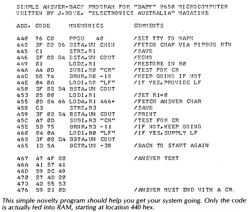 I started with the shortest program I could find to start with. That program was from the March 1977 edition of Electronics Australia and was written by Jim Rowe in July of 1976 to test a Signetics development board, the PC1500. I wonder if he would care if someone in 2018 is typing a program, he wrote over 40 years ago, into a newly built 2650 microcomputer, at 110 baud?
All was looking good, until I ran a memory test program to test out the full 31K of RAM (32K minus the 1K ROM image) that was installed. I was testing blocks of RAM and everything was looking good, until I ran the test at address 0x2000h and above. As soon as the memory test got to this point, it was telling me I couldn’t write to memory. I expected this memory space to be RAM, so what was going on?
Part 3 will detail how I find the problem and the changes I make to the prototype.